
ML model predicts tracker radio coverage, eliminating dead zones in 49 MW European retrofit
A company used machine learning on radio chip telemetry to predict 2.4 GHz signal propagation across moving tracker fields, replacing static rule-of-thumb gateway placement. A retrofit of five European plants demonstrated that computed gateway positions eliminated angle-dependent communication dead zones without field trial and error.
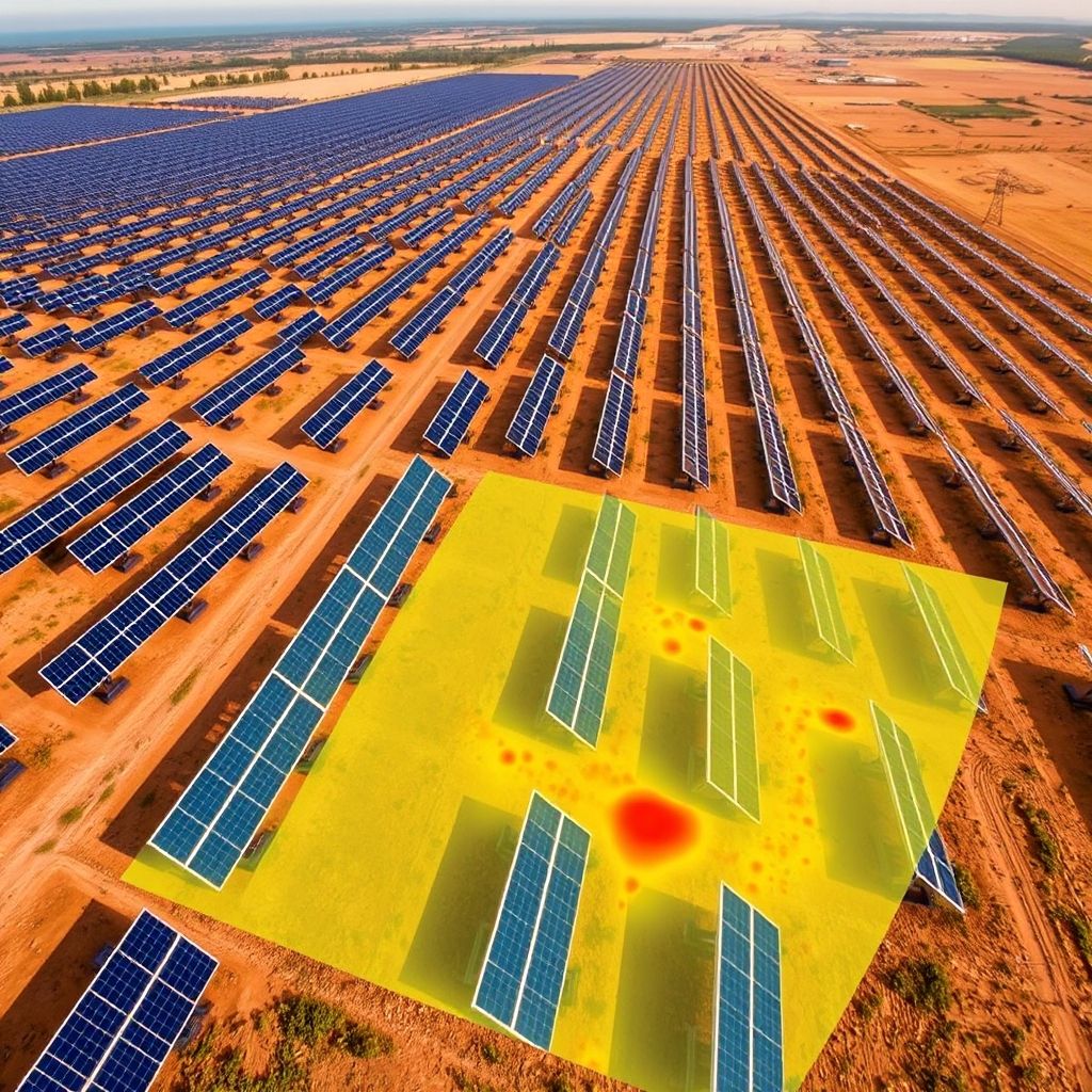
When a single-axis tracker loses its wireless connection to the plant controller, it may cease tracking, remain fixed at a particular angle, or fail to execute a coordinated stow maneuver, contingent upon its configured failsafe protocols. As detailed in reports from pv magazine, the sector’s prevailing methodology relies on a heuristic: installing a gateway at intervals of several rows, positioning it in proximity to the controller, and depending on the Zigbee mesh protocol to sustain network connectivity.
The moving signal problem
Unlike fixed-tilt installations, single-axis trackers comprise extensive, mobile metallic frameworks that incorporate torque tubes, bearings, module frames, and photovoltaic modules. This heavy metal construction disrupts the 2.4 GHz frequencies employed by Zigbee protocols via reflection, absorption, and diffraction. Because the array’s geometry is dynamic, the surrounding radio conditions shift continuously throughout the day. As rows transition from steep east-facing angles at sunrise, through level positions at midday, to steep west-facing angles at sunset, the physical trajectory for radio waves remains in a state of constant change. Consequently, a connection that functions flawlessly at noon may suffer degradation or total failure at high tilt angles during the early morning or late afternoon.
Data-driven design approach
- Standard tracker control systems typically utilize pre-fabricated gateway hardware that fails to expose low-level radio data, blocking an empirical view of mesh behavior on active sites.
- The firm engineered a proprietary gateway capable of reading radio chip-level telemetry directly, logging per-link signal strength, link quality, and retransmissions while the system operated normally.
- This methodology produced an extensive real-world dataset detailing 2.4 GHz signal propagation across tracker fields as the rows shifted.
- A machine-learning algorithm was developed using data from multiple dozen locations representing several hundred megawatts of capacity, encompassing varied tracker designs, plant arrangements, and terrain conditions.
- The algorithm forecasts radio propagation based on panel tilt angle, the specific structure or tracker type, and the overall plant layout.
- It tailors its forecasts to the unique hardware and topography of each individual project, avoiding assumptions about a generic propagation environment.
- The resulting coverage map allows for evaluation across the entire spectrum of tracker angles prior to the installation of any single gateway.
- Dead zones were eliminated across the full range of tracker angles during the retrofit.
Hardware architecture shift
A propagation model is only useful if the physical architecture allows engineers to act on its recommendations. In conventional designs, gateways are often physically tied to network control units. This constraint dictates their position based on where electrical cabinets stand, which may be nowhere near the radio-frequency optimal location. The company’s new architecture decouples these components, "deporting" gateways from the main controller. This independence allows hardware to be placed exactly where the simulation indicates coverage is strongest, regardless of the controller’s position. In this setup, the software identifies the required network nodes, while the hardware configuration makes it possible to deploy them at those specific coordinates.
The company recently retrofitted this tracker control system across a portfolio of five operating plants in Europe. These sites range from 5 MW to 23 MW, totaling roughly 49 MW. The plants suffered from two chronic issues: control cabinets failing in the field and persistent communication dead zones. Engineers modelled each existing layout using the simulation tool to determine the necessary changes.
Consider a specific 11 MW site with around 340 trackers split into two zones. The original design listed four gateways on paper, but in practice, this meant only two radio locations. Because the pairs of radios were stacked at the same points, doubling the hardware created redundancy rather than coverage. During the retrofit, the simulation determined how many deported gateways each zone actually required and exactly where to place them among the rows. The process required no field trial and error, and no additional hardware was added after commissioning.
Source: pv magazine. This article is an original Luminity report based on the linked source.